When I decided to go all in on this project, I knew I was going to have to get the body up on a frame jig to get it level to factory specs. Replacing as much body sheet metal as I was, a frame jig was a necessity. I decided it was an easy enough project and there were plenty of resources online for examples.
My initial design was going to be a standard 2″ x 2″ square tube design like the the crew over at the AMD Installation Center use for all of their projects, and they were very helpful in giving us some feedback. I also had found a really good resource on Facebook from our friend Robin McQueen and his frame jig project.
Two things are needed to start this project. First and foremost are a set of factory service and body manuals, no project should start without them. There are plenty of sources out there for both print reproductions and digital formats. We chose to have printed reproductions, but no matter what format you chose, they are worth the cost to have.
The second thing that is helpful, especially for building the frame jig is a frame alignment specification and datum sheet. I was able to find a service on eBay that ships you a printed copy of both for cheap. The datum sheet is especially useful because the uprights/stanchions the body rests on are based on the measurements along the datum line.
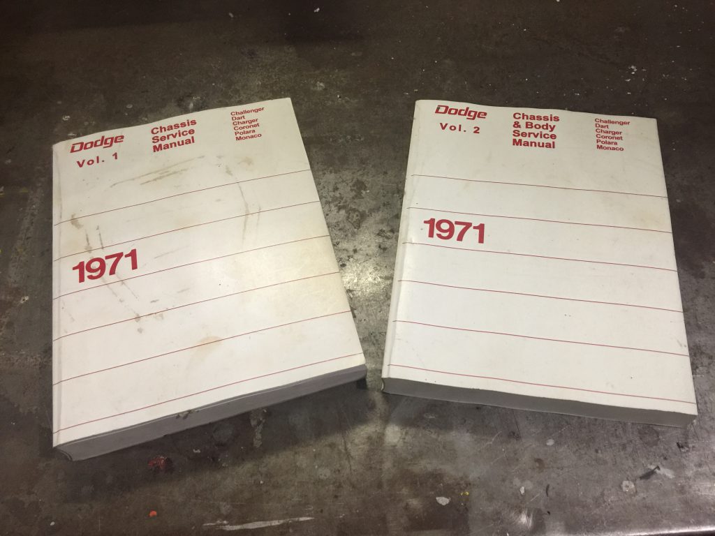
A set of factory shop manuals is a must for any project. 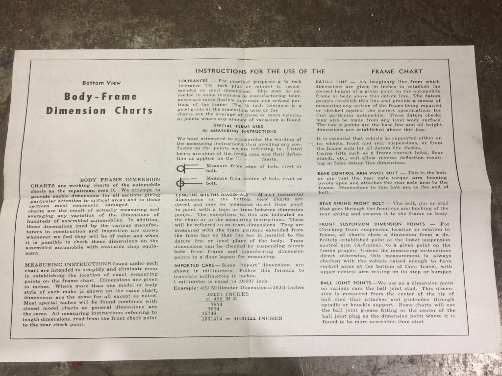
Page 1 – Instructions of the Body Frame Dimension Chart 
Page 2 – Alignment Specifications of the Body Frame Dimension Chart 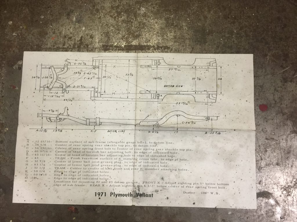
Page 3 – Chassis and Datum Information of the Body Frame Dimension Chart
My Dad seems to always come through with something when I least expect it to help out with the garage and project. To our luck, his company was getting rid of a bunch of custom steel horses they used for unloading some heavy machinery. He texted me a couple of pics and asked if I could use them for anything in the garage. Texted him back and said “Hell yeah!” I could use them for the frame jig.
So my Dad brought them over and I ended up with three 8′ long horses and one shorter one about 4′ long. Two of the long ones and the short one had a 1′ tall extension on the top surface that I had to remove.
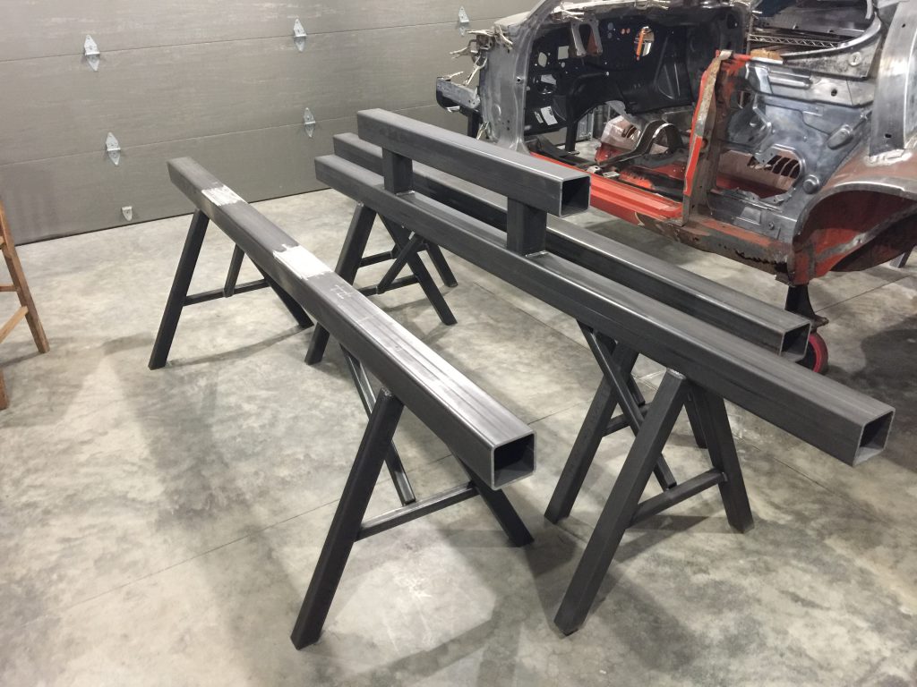
The raw material for fabricating our custom frame jig. 
The main structure of the table pat of the frame jig. 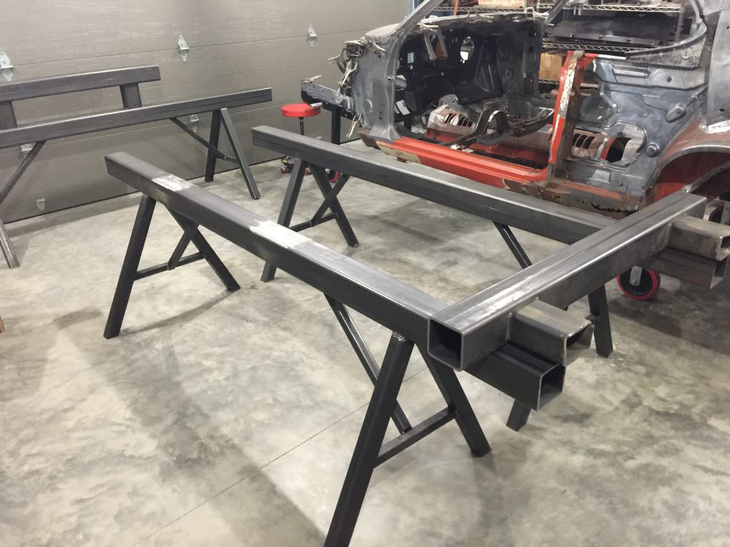
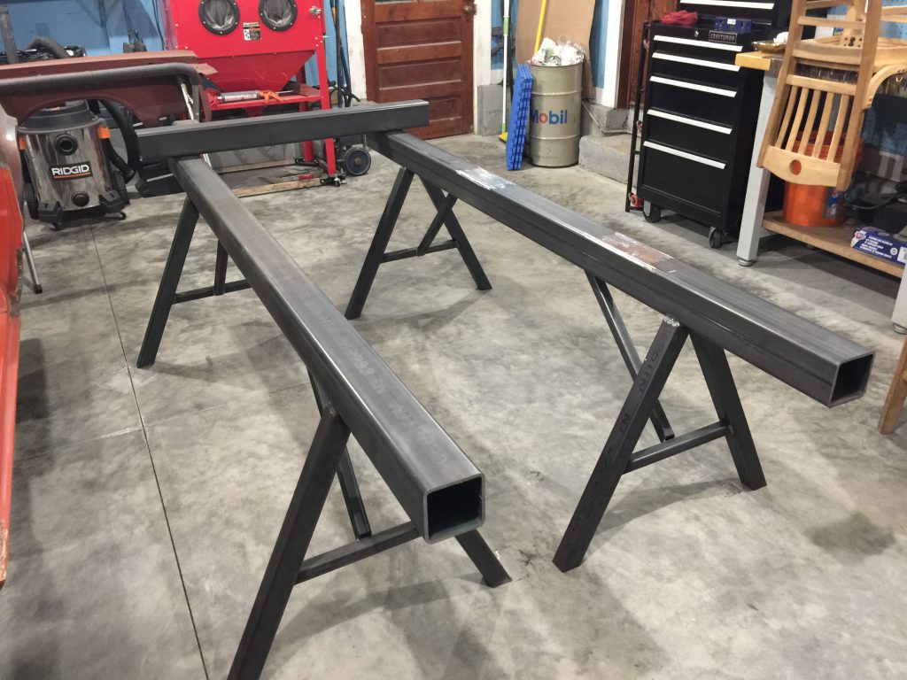
My goal here was to end up with two 8′ long horses to serve as the table part of the frame jig. The rest of the material would be cut up and used in other areas. The main tubing is 4″ x 0.25″ square tube, and the supports are 1 1/4″ square tube, way more beefy than we need, but it was free!
Using cut-off wheels and a grinder, the first thing I did was get the welded on extensions removed off of the surface of the frame rails. The horses were tall, I needed to cut some material off of the bottom of the legs, but I didn’t feel like messing with the already welded cross braces, so I cut them down as far as I could.
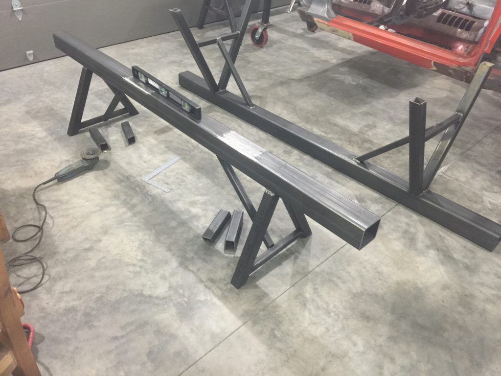
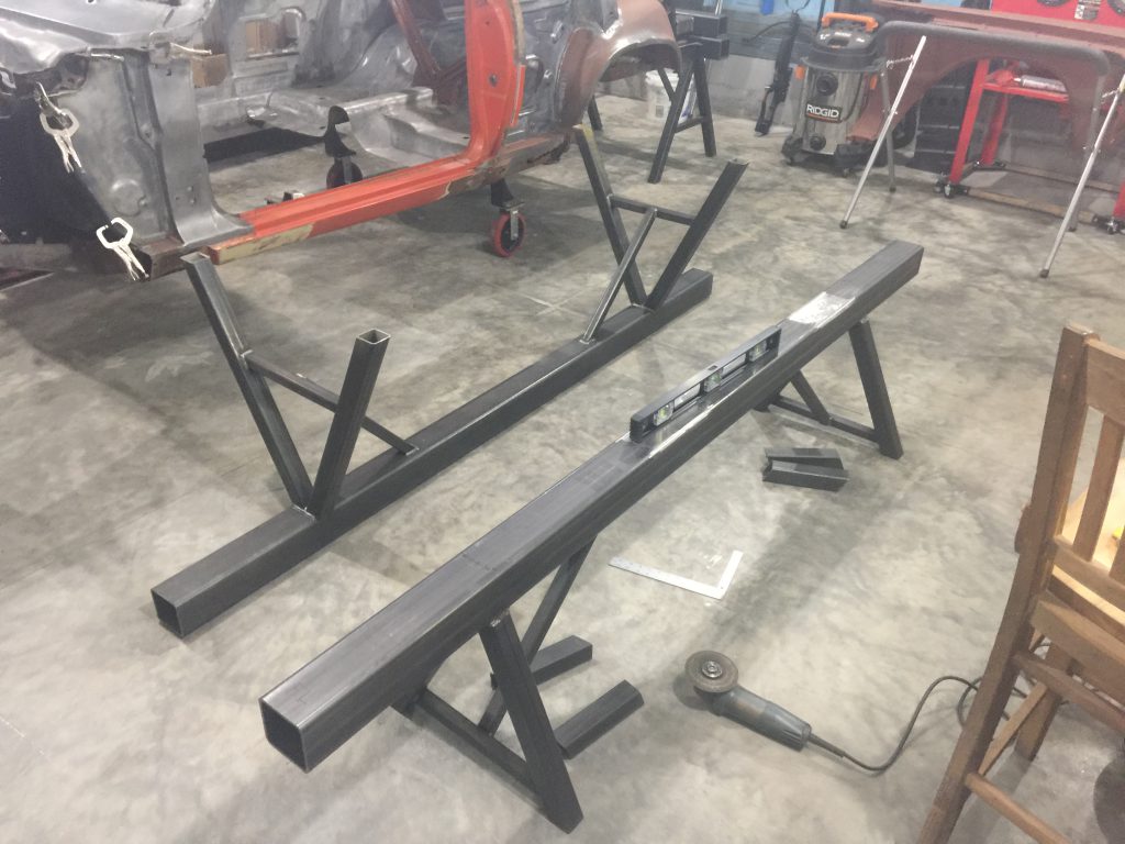
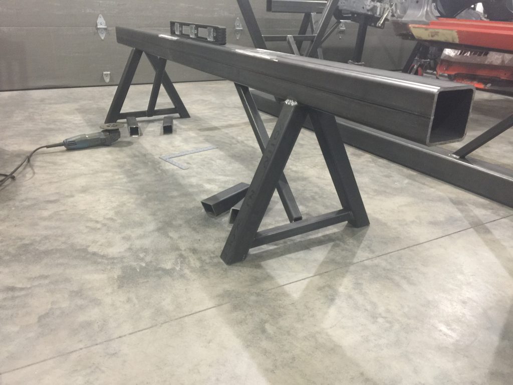
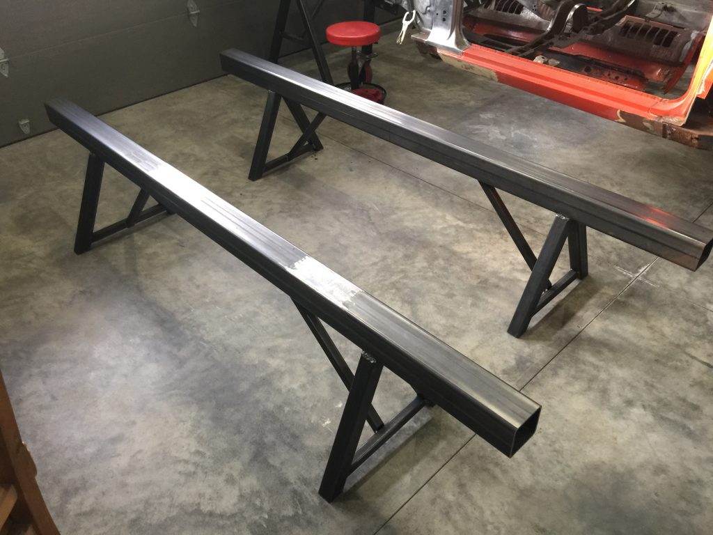
These two horses serve as the frame jig table rails, they are the foundation of the jig.
I used a laser, a level and some squares and I measured from the top surface of the top rails down, to make sure we were level at all eight legs with the rail surface and not the floor. The results were great as the laser showed that all four corners were level.
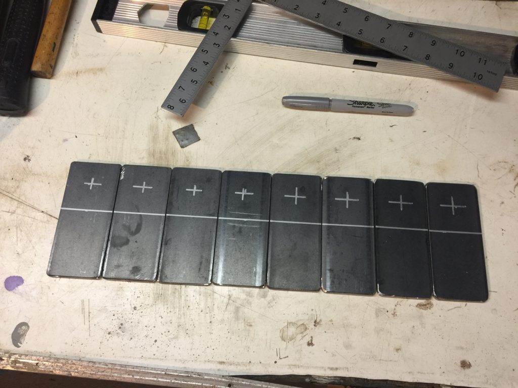
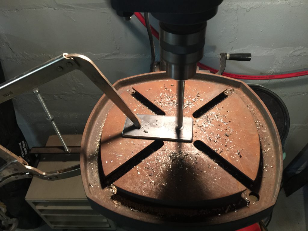
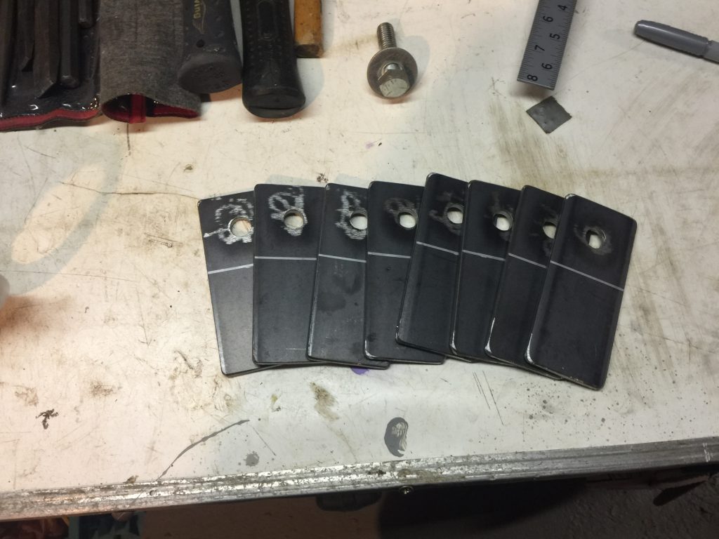
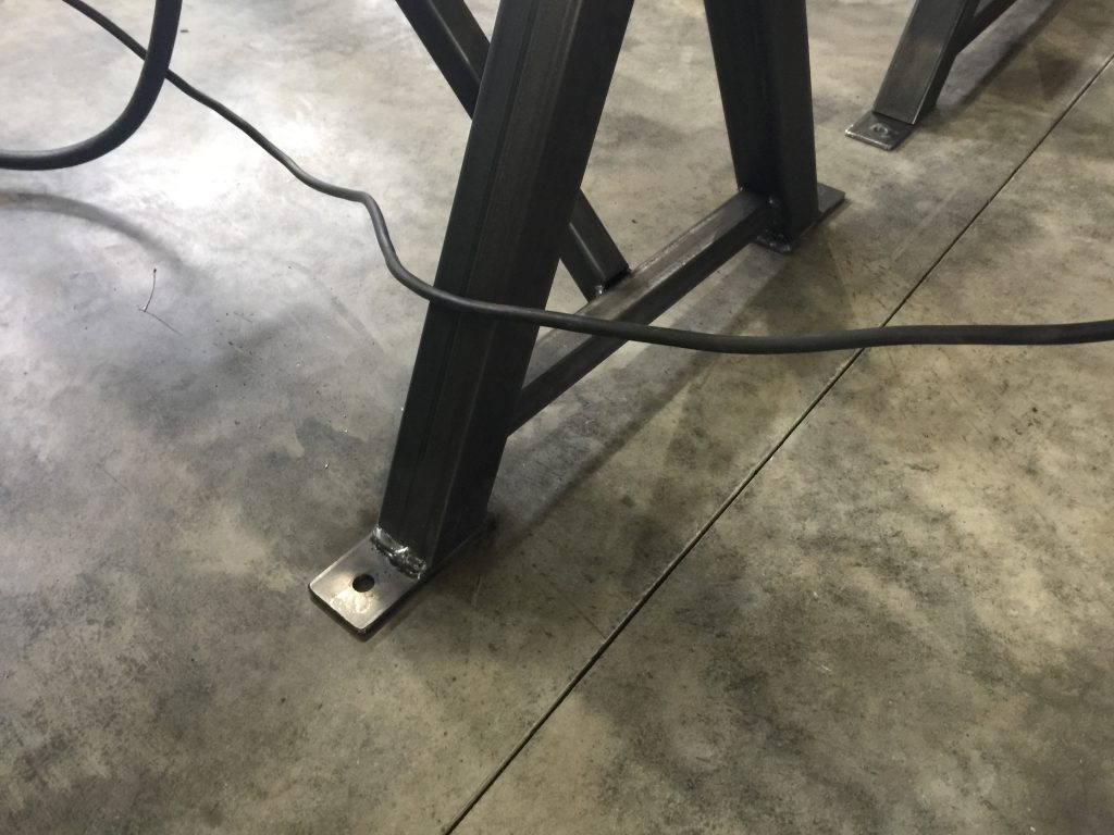
The next step was to make some 1/4″ plate tabs to weld to the bottoms of all eight legs. The tabs would allow me to bolt the horses to a 2″ x 4″ x 0.25″ cross brace. The two cross braces would allow me to secure the two horses together and square them the each other. It would also allow me a place to mount our casters to get the jig up on wheels.

